
Apparatus Designed and Built by Physicists who have taught in the Advanced Undergraduate Lab

Introduction
TeachSpin’s collaboration with the German company, GAMPT mbH (www.gampt.de), adds to the TeachSpin repertoire not only the elegant GAMPT ultrasonics apparatus, but also TeachSpin-developed curriculum and student manuals which focus on the physics of wave propagation, transferable experimental skills, self-discovery experiments, and student projects for independent study. We suspect that when you first read ‘ultrasonics’, you immediately thought of medical applications: ultrasonic imaging of the fetus, of breast tumors, blood flow measurements from Doppler frequency shifts, and, perhaps, procedures for shattering kidney stones with focused high-power ultrasonic waves.
Yes, this equipment can certainly give your students the opportunity to study medical diagnostic and treatment techniques, but, with the same hardware, students will investigate, experimentally, an important field of physics, which has been neglected in most of our upper-division laboratory courses. The following is a brief first look at a few of the many possibilities that TeachSpin will now be offering.
The parameters of interest in ultrasonic measurements are frequency, wavelength, propagation velocity, acoustic impedance, and absorption coefficient. The frequency is determined by the electronic oscillator which drives piezoelectric transducers that, in turn, create an ultrasonic compression wave. But these transducers can also serve as ultrasonic receivers (or microphones), converting ultrasonic energy into electrical signals. GAMPT has carefully crafted various types of electronics and transducers, both pulsed and continuous-wave, which are customized for various ultrasonic experiments. All of these units are available through TeachSpin.
A description of the two of major electronic units,'Echoscope GAMPT-scan’, a pulse unit, and ‘Wave Generator SC 500’, a variable-frequency continuous-wave system highlights the possibilities.
The 'Echoscope' is used for a wide variety of pulsed experiments including important physics investigations, as well as medical applications. This is probably the most versatile unit, especially with the 1, 2, and 4 MHz transducers that can serve as both transmitter and receiver.
Ultrasonic waves, like electromagnetic waves, exhibit reflections from material boundaries when there is a discontinuity of the acoustic impedance at the boundary. An example of this is shown in Figure 1, where we are injecting an ultrasonic compression wave into a stack consisting of an acrylic cylinder of height 41.3 mm on top of an aluminum block that is 24.2 mm high. The sound waves encounter two significant boundaries: first, at the acrylic-aluminum interface, and then at the aluminum-air end. The single transducer on top creates the short ultrasonic driving pulse, and also acts as the receiver to detect the time-delayed ultrasonic echoes. The first impedance discontinuity encountered by the acoustic wave (the acrylic-aluminum interface) causes a reflected compression wave which travels back to the transducer.
The first ‘echo’, shown in Figure 2, is the signal from that reflection. The round-trip travel time is 30 μs, so the velocity of this 1 MHz wave is 2 x 41.3 mm/30 μs or or 2750 m/s. But at this same interface between the two materials, some of the wave is transmitted into the aluminum. Next, it reflects back from the aluminum-air interface and returns through both the aluminum and the acrylic. This echo travels an additional 48.4 mm. See if you can show, from the ‘scope trace, that the velocity of the sound wave in this 6061 aluminum alloy is about 6000 m/s. Why are there additional echo signals? Can you account for them?

Fig. 1: The echoscope
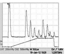
Fig. 2: Ultrasonic Echos on a 10 us/div time base
Figure 3 shows a water tank with a rectangular acrylic slab of 10 mm thickness obliquely immersed in it. In this experiment, two transducers are used, one to inject an ultrasonic compression pulse into the tank and a second one to receive the ultrasonic waves that propagate to the opposite side. The oscilloscope signals are shown in Figure 4.
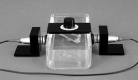
Fig. 3: Transmission Ultrasonics

Fig. 4: Pulse transmission signals on a 10 us/div time base
Notice that two pulses are picked up at the receiver. The reason for the two signals is the creation, at the first water-acrylic interface, of two kinds of waves in the acrylic slab: a longitudinal (compression) wave, and a transverse (shear) wave. In the solid medium, this shear wave propagates at a significantly lower velocity than the compression wave. However, a shear wave will not propagate in a liquid. Thus, the shear wave in the solid, encountering the interface at an oblique angle, launches only a compression wave in the liquid, which then travels to the receiver. This set-up can be used to determine the velocity of both the compression and shear waves in the solid, and the critical angle for total internal reflection, as well as the velocity of sound and the attenuation coefficient for compression waves propagating in the liquid. In geophysics, compression and shear waves moving through the earth are called p-waves and s-waves.
The SC500 is a variable (1–20 MHz) high-power, continuous-wave, signal generator with a built-in power supply for operating a solid-state laser. One of the interesting explorations is the Debye-Sears effect, the diffraction of light from a 3-d acoustic grating created by an ultrasonic standing wave.

Fig.5: Debye-Sears set up
Figure 5 shows the experimental set-up to explore the Debye-Sears effect. The broadband ultrasonic transducer is mounted on the top of the water-filled cell, in a support structure which allows the student to optimize the standing wave in the water. The laser is mounted on the side of the cell so that its horizontal light beam will be diffracted by the acoustic standing wave. The sound pressure field generates periodic changes in the index of refraction which act as a ‘grating’.
The mirror on the left is used simply to extend the path length of the light beam, which is then projected on the flat screen. The insert in Figure 5 clearly shows the diffraction pattern of the green laser beam by a 5 MHz ultrasonic standing wave. This experiment not only demonstrates the fascinating and highly applicable acousto-optic effect, but it also can be used to measure the wavelength of sound in an optically transparent medium as a function of frequency.
These are only a few examples of the experiments that TeachSpin is incorporating into its in-progress student/faculty manual.
As a list of just a few of the topics to which it relates surely indicates, UltraSonics certainly deserves a place in both the intermediate and advanced lab. These topics range from geophysics, non-destructive testing, hidden defects in materials, non-invasive flow measurement, piezoelectricity, and acousto-optics to consumer products such as ultrasonic cleaners, humidifiers, liquid level indicators, ultrasonic welding, distance measurement and last, but certainly not least, to medical physics applications.Detailed descriptions of the kits we currently offer are on our price list page and on the last pages of the pdf versions.