
Apparatus Designed and Built by Physicists who have taught in the Advanced Undergraduate Lab
Optical Pumping

-
Optical Pumping of Rubidium Atoms, Rb85 and Rb87
-
Explore Magnetic Hyperfine Interactions of Rubidium
-
Observe Zero-Field Transitions
-
Confirm Breit-Rabi Equation
-
Observe Double Quantum Transitions
-
Study Rabi Oscillations
-
Measure Optical Pumping Times
-
Study Temperature Dependence of Atomic Parameters Optical Pumping of Rubidium Gas
Introduction
Optical Pumping is a widely used and powerful technique for exploring atomic energy states, atomic transitions, and atomic collisions using electromagnetism in the form of light, radio frequency, and uniform constant magnetic fields. TeachSpin’s Optical Pumping apparatus explores the atomic physics of both isotopes of natural rubidium.
The rubidium atom is an ideal model system for students to study. Its energy states, in an externally applied uniform magnetic field, can be understood using a semi-classical model. This model describes the coupling of a single electronic orbital and spin angular momentum with the nuclear spin angular momentum and of the coupled system to the external field. The experimental determination of these atomic energy states can be compared to the theoretical predictions of the Briet-Rabi equation. The two isotopes of rubidium, Rb85 and Rb87, with different nuclear magnetic moments, make the experimental data even richer.
TeachSpin's Optical Pumping Lab apparatus allows the student to explore a wealth of atomic physics, including temperature dependent cross-sections for photon absorption, zero magnetic field transitions, spin-spin collision processes, field inversion measurements, Rabi oscillation of the atomic magnetic moment, optical pumping times, and other atomic physics experiments. It is only a small exaggeration to claim these experiments constitute an atomic physics course.
Instrument

The basic features of the experimental set up of TeachSpin's Optical Pumping apparatus
are shown in Figure 1. Rubidium resonance light from a heated rf discharge lamp is
collimated by a plano-convex lens and passes approximately parallel through an
interference filter, so that only the 795 nm line is transmitted. The light then passes
through a linear polarizer and a quarter wave plate to produce a circularly polarized
beam of light. This monochromatic, circularly polarized, light passes into the oven and
through the rubidium vapor absorption cell. The diverging light is focused by a second
plano-convex lens onto the photodiode detector.
The oven, with its absorption cell, resides inside two pairs of Helmholtz coils. The
studentmust align the instrument so that the absorption cell’s axis (the light path) lies
along thedirection of the local Earth’s magnetic field. One Helmholtz pair is used to
cancel the vertical component of the Earth’s magnetic field. The second pair is used to
create auniform horizontal magnetic field in opposition to the horizontal component of
the Earth’s field. Transitions are induced among the atomic energy levels by the radio frequency magnetic field which is applied transverse to the optic axis. These transitions are observed as changes in the light intensity as measured by the photodiode optical detector.
The open construction of the Optical Pumping system allows students to manipulate the location of all the optical components. The can even insert the quarter wave plate and the linear polarizer in the wrong order which becomes an important learning experience.

Experiments
Students will explore the interaction of the alkali atom with a weak magnetic field, as described by the theoretical perturbation calculations known as the Briet-Rabi equation. This equation is:


W is the interaction energy, ΔW is the hyperfine splitting energy and B is the externally applied magnetic field
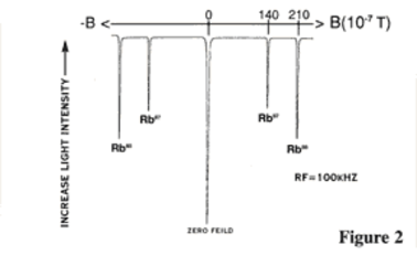
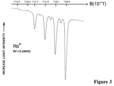
Figure 2 (below) shows the optical pumping signals for zero and very low magnetic fields. Both the Rb85and Rb87 isotopes produce only unresolved single lines in these low fields. However, when the magnetic field is increased, each single line splits into resolved hyperfine lines, as shown in Figure 3 (below). This data can be compared to the Briet-Rabi predictions. Double quantum transitions are also detected on this data. They can be studied as a function of rf power.
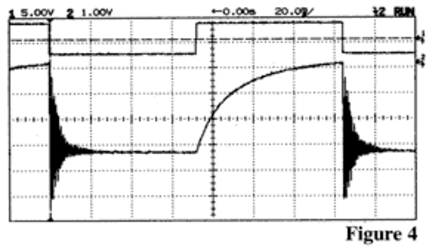
Both optical pumping times and the so-called Rabi oscillations can be studied by gating the rf power on and off at low magnetic fields.
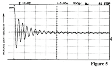
Figure 4 (below) shows a measure of the optical pumping time when the rf power has been turned off and Figure 5 (below) is an exploded view of the signal after the rf has been gated on. It clearly shows the oscillations of the transmitted light which are interpreted as precession of the atomic magnetization about the rf magnetic field. They can be studied as a function of rf power.
Other experiments include (but are not limited to) magnetic field reversal, photon absorption, spin exchange, effect of buffer gases on optical pumping and temperature dependence of all of the above experiments. The instrument even includes a second mounted linear polarizer for students to study circularly polarized light.
Additional Resources
Specifications
Accessories
Absorption Cell:
Natural Rb with 30 Torr Neon
Lamp:
RF Discharge of Isotopically Enriched Rb (63% Rb87)
Oven:
PID Controller,
Range; Ambient – 100 °C
Res. 0.1°C, Reg. 0.05 °C/hr
Optics:
50 mm Diameter
Interference Filter
2 Linear Polarizers and 1/4 Retarder Plate in 360° Rotation Mounts
2 Plano-Convex Lenses, f = 50 mm
Photodiode Detector:
Low-noise Current-to-Voltage Preamplifier
Bandwidth 0.1 Hz - 1 kHz
Noise: 20 µ Vp-p with Rgain = 1 M Ohm
Magnetic Field of Precision Helmholtz Coils:
Vertical:
0 – 1.4 x 10⁻⁴ T,
Stability, 2 x 10⁻⁷ T/hr,
Horizontal:
8 x 10⁻⁴ T (internal supply)
22 x 10-4 T (external supply)
Stability, 4 x 10⁻⁷ T/hr
Homogeneity > 2 x 10⁻⁴ over cell
Horizontal Sweep: 0 – 10-4 T,
Time 1, 2, 5 . . . 1,000s
Stability 2 x 10⁻⁷ T/hr
External Modulation Input
Included:
Black Cloth Shroud
Mounted Linear Polarizer
Instruction Manual
Additional:
High Current Supply
Different Absorption Cells
RF Signal Generator
Nonmagnetic Table
Circuit Diagrams
Extended Warranty
RF Amplifier:
10 kHz – 100 MHz
Input Impedance = 50 Ohms.
Output 150 mW, 100 mA Max.
Detector Amplifier:
Amplifier: Gain, 1, 2, 5,. . . 1000
Low-Pass, 12 db/oct
Time Constants, 1ms, 10 ms . . . 3s
Dimensions:
Electronics 13’ x 15” x 10”
Exp. Table 28” x 15” x 16”
Warranty:
Two Years, parts and labor