
Apparatus Designed and Built by Physicists who have taught in the Advanced Undergraduate Lab
Magnetic Torque
Magnetic Moments Interacting with Magnetic Fields
Measure Magnetic Moment Four Independent Ways
-
Static Torque
-
Harmonic Oscillation
-
PrecessionMagnetic
-
Force
Gyromagnetic Ratio
"Magnetic Resonance" Spin-Flip Analog

Upgrades are Now available for instruments purchased before 2010!
Introduction
Magnetic Torque offers students an opportunity not only to make quantitative measurements involving electromagnetism, torque and simple harmonic motion but also to study, quantitatively, the phenomenon of precession.
This instrument is equally at home in an Honors Freshman Lab, an Intermediate Sophomore/Junior physics laboratory and, as an analog for Nuclear Magnetic Resonance, in either a Modern Physics or Advanced Senior Laboratory.
Although every introductory physics textbook discusses the interactions of a current loop with magnetic fields, Magnetic Torque and Magnetic Force are the only teaching apparatus capable of demonstrating such interactions.
Using small magnetized disks that act like magnetic dipoles, students measure phenomena that result from magnetic torque or magnetic force.
Students can determine the dipole moment of the disk in a variety of ways using fundamental E&M and mechanics principles.
In addition, Mt1-A can be used to demonstrate basic principles of magnetic resonance including a Pulsed NMR spin-flip.
Magnetic Torque now comes with the Magnetic Force Balance Kit.
Note: Significant improvements have been made to the original Magnetic Torque apparatus shown below. We have developed an entirely new pump system which can be installed in your apparatus. Other changes included a new strobe which will improve the accuracy of student measurements.
Contact us to see how your original model can be upgraded.
Instrument
All Torque Measurements are done on a cue ball which has a magnetized disk imbedded at its center.
-
The handle is oriented along the direction of the magnetic moment.
-
The ball floats on an ultra low-friction bearing located at the center of the Helmholtz-like coils.
The electronics system is self contained.
-
The power supply has a DC current source for both the coils and the electronics for a strobe light and frequency counter.
-
The counter measures the rotational frequency of the spinning ball.
-
A compressed air source for the bearing is also included.
Force measurements are carried out on a magnetized disk supported in a gimbal.
-
A magnet, just like the one inside the ball, is set into a gimbal, a plastic holder free to rotate.
-
The gimbal is suspended from a spring which can be calibrated using the one gram steel spheres provided. (The spheres will adhere to the magnet.)
-
The power supply can be switched to make the currents in the two coils flow in opposite directions, creating a field gradient at the center of the coils.
-
The spring is suspended from a brass rod protruding from the plastic cap. The brass rod can be raised or lowered to return the gimbal to its initial position allowing for null measurements.
The spinning ball can be used to demonstrate a classical model of magnetic resonance, including the "spin-flip " that creates a spin echo.
-
A millitesla uniform magnetic field, created by permanent magnets and iron shims can be slipped over the air bearing.
-
Manually rotating the unit at the Larmor precession frequency of the spinning sphere visually demonstrates the "spin-flip" process.
-
While the rate of rotation is analogous to the Larmor frequency, the time of rotation models the pulse width of pulsed NMR.
Experiments
-
CalPoly SLO: A Novel Way to Spin the Sphere
-
Demonstrating Magnetic Resonance and the Pulsed NMR Spin Flip
You may also enjoy taking a look at our Pulsed/CW NMR apparatus for more advanced experiments.
Magnetic Torque experiments include quantitative measurements of electromagnetism, magnetic and gravitational torque, simple harmonic motion, and precession along with an introduction to the concepts of gyromagnetic ratio, nuclear magnetic resonance and the Pulsed NMR spin-flip.
Students develop an operational definition of magnetic moment and then measure the magnetic moment of the magntized disk imbedded in the snooker ball five different ways. Because each method involves a different set of parameters, more sophisticated students are able to evaluate the limitations of each type of measurement. The Magnetic Force Tower Accessory offers a dramatic contrast between the torque produced by a uniform magnetic field and the forces generated in a field gradient.
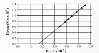
Magnetic Torque Equals Gravitational Torque
This is a statics experiment. A gravitational torque is applied to the ball by a weight on an aluminum arm inserted in the ball's handle.
When the magnetic torque is adjusted to equal the gravitational torque:
µ × B = r × mg
Here, r is the radial distance of "m" from the center of the ball.
Since B and mg are measurable quantities, µ can be determined.
A graph of the gravitational torque, rmg, as a function of the magnetic field B yields a straight line whose slope is the magnetic moment µ. This experiment also provides an "operational definition" of magnetic moment; a one unit magnetic moment experiences a one N-m torque in a one tesla field. Simple algebra shows N-m/tesla=amp-m2.
Notice that the line on the graph of Torque vs. Magnetic Field does not go through (0,0). This is because the magnetic torque must balance the combined torque of both the mass and the aluminum arm.
The intercept indicates the B field needed to balance just the torque of the aluminum rod but does not affect the slope from which µ is calculated.

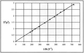
Harmonic Oscillation
The cue ball, supported in a uniform magnetic field by the air bearing, acts like a
spherical physical pendulum.
Its oscillations are described by:
- |µ × B| = I(d2q/dt2)
where I is the moment of inertia and q is the angular displacement.
For small q, the motion is simple harmonic with a period T given by:
A sample of one student's data is given to the right. The magnitude of the magnetic
moment canbe calculated from the slope of the line.
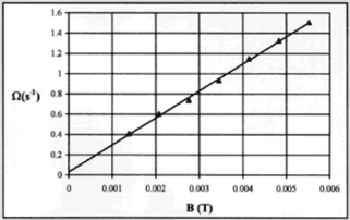
Precessional Motion
Spinning the ball gives it angular momentum L, which can be determined by measuring its rotational frequency using the built-in strobe light and counter.
In a uniform magnetic field B, the precessional motion of the spinning ball with its "intrinsic" magnetic moment µ is described by: µ × B = dL/dt
The solution for the precessional frequency is:
Wp = µB/L One way to extract the magnetic moment from this phenomenon is to measure the precessional frequency as a function of magnetic field for a given angular momentum.
A sample of one student's data for this measurement is shown to the right. The linear behavior confirms the theory and the slope gives the third independent measure of µ.
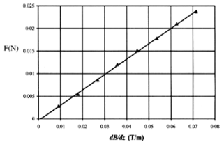
Magnetic Force
There are three objectives to the experiments which utilize the magnetized disk suspended from the calibrated spring:
To demonstrate that there is no net force on a magnetic dipole in a uniform magnetic field, only a net torque.
To recognize that there is a net force on a magnetic dipole in the presence of a magnetic field gradient.
To measure the magnetic moment using the relation:
F = µz(dB/dz)
Student data for magnetic force is shown on the right. The magnitude of this dipole moment will be close to those found for the dipole imbedded in the cue ball.
With the addition of a horizontal uniform rotating magnetic field, the Mt1-A becomes an instrument to demonstrate a classical analog for magnetic resonance. [Magnetic Torque with Rotating Field Attachment]
Magnetic resonance is observed on atomic size particles that have both intrinsic magnetic moment and angular momentum.The cue ball can be made to mimic the atomic particles by spinning it so that it has angular momentum as well as its "intrinsic" magnetic moment.
The horizontal magnetic field is manually rotated by the demonstrator at the Larmor precession frequency for the particular angular momentum "spun-up." A 90° or 180° nutation spin can easily be produced.
Given the approximate magnitude of the rotating field, students can even estimate the time necessary to nutate the ball by 90°.
Such demonstrations significantly enhance a student's understanding of the complexities of rotating coordinate systems, effective fields, and spin nutation that are fundamental to mastering the principles of magnetic resonance.
Additional Resources
Specifications
Includes:
magnet coils, air bearing, power supply, air pump,
one magnetic sphere, electronics for strobe light and counter,
gravitational torque arm and gimbal with calibrated spring.
Coils:
195 Turns; #18 Gauge
Inner radius = 10 cm; Outer radius = 11.4 cm
Separation = 12.4 cm
Current:
0-4 A
Electromagnetic Field:
0-5 mT
Magnetic Moment:
0.4 A-m²
Cue Ball:
Mass = 140 g
Radius = 2.70 c
Strobe Frequency:
3-9 Hz
Spring Constant:
1.0 N/m
Rotating Magnetic Field:
1 mT